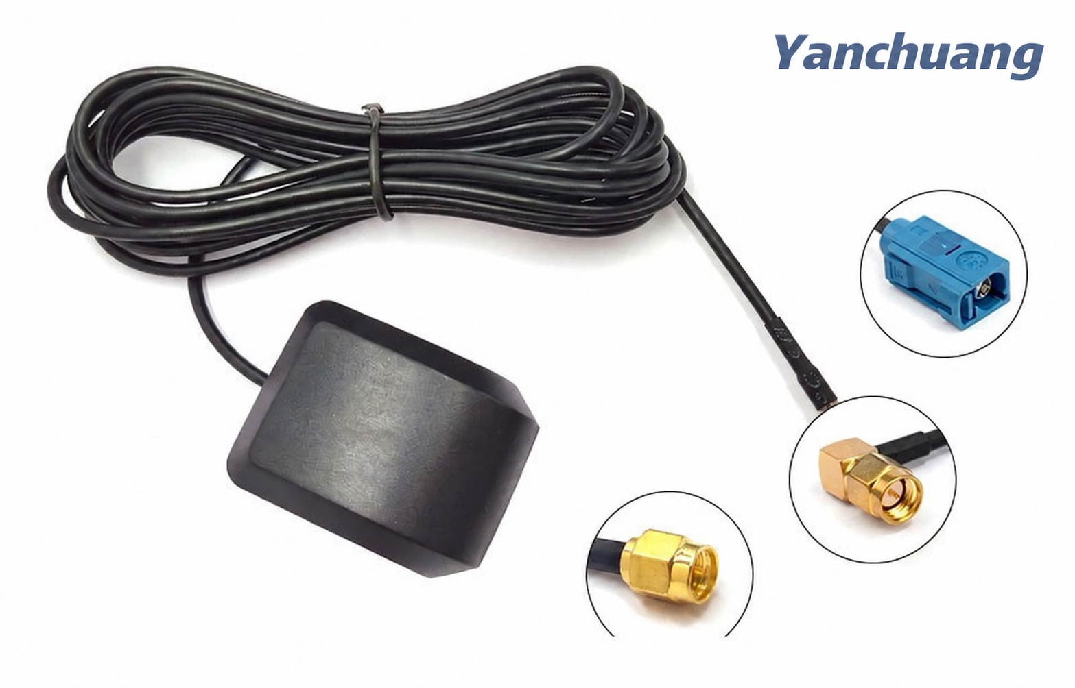
The GPS/Beidou navigation antenna is the "ear" of the navigation system, responsible for receiving extremely weak radio signals from navigation satellites in space tens of thousands of kilometers away. Its performance directly determines the accuracy, speed, and stability of positioning.
The GPS/Beidou navigation antenna is the "ear" of the navigation system, responsible for receiving extremely weak radio signals from navigation satellites in space tens of thousands of kilometers away. Its performance directly determines the accuracy, speed, and stability of positioning.
1、 Core functions and importance
The main tasks of navigation antennas are:
Receiving signals: Receive L-band microwave signals (with frequencies ranging from approximately 1.1GHz to 1.6GHz) emitted by navigation satellites such as GPS (United States), Beidou (China), GLONASS (Russia), and Galileo (European Union) within line of sight.
Impedance matching: Achieving impedance conversion between free space (impedance of approximately 377 Ω) and the receiver RF front-end (usually 50 Ω) to ensure efficient signal transmission.
Right handed circularly polarized: Navigation satellite signals are right-handed circularly polarized waves, so the antenna must also be designed as a right-handed circularly polarized antenna in order to maximize signal energy reception and suppress left-handed polarization interference (such as reflected waves).
Anti multipath effect: Good antenna design can to some extent suppress signals reflected from the ground or buildings, which can delay arrival and cause "multipath errors", leading to positioning drift.
Provide gain: amplify useful signals from the sky (especially in the zenith direction) while suppressing interference signals from the ground.
Simple metaphor: If the navigation chip is the "brain", then the antenna is the "ear". An ear with poor hearing (low sensitivity) and susceptibility to mishearing (poor anti-interference ability), even the smartest brain cannot make accurate judgments.
2、 Main technical types
According to application scenarios and performance requirements, there are several mainstream navigation antennas:
1. Passive antenna
Features: No amplification circuit included, simple structure, low cost, no need for power supply.
Disadvantages: High signal loss, highly sensitive to cable length and quality, usually required to be used close to the receiver.
Application: Early or low-cost navigation devices, antennas built into mobile phone motherboards (often reused with Wi Fi/Bluetooth antennas, with average performance).
2. Active antenna - currently the absolute mainstream
Feature: The antenna body is closely followed by a low-noise amplifier. This LNA is crucial as it serves two purposes:
Amplify weak signals: Amplify satellite signals before entering the cable to compensate for cable transmission losses.
Reduce system noise: The noise figure of the entire system is mainly determined by the first stage amplifier, and an excellent LNA can significantly improve the signal-to-noise ratio.
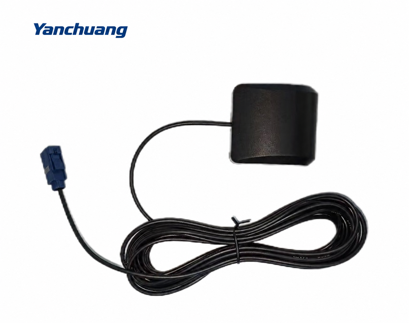
Structure: usually consisting of "antenna radiation plate+ceramic medium+LNA amplifier+shielding cover".
Power supply: A coaxial cable is required to provide a DC bias voltage (usually 3.3V or 5V) from the receiver.
Applications: Almost all professional and consumer level fields such as car navigation, drones, surveying, precision agriculture, ships, etc.
3、 Interpretation of Key Performance Parameters
When selecting or evaluating a navigation antenna, the following parameters should be considered:
Gain: Peak gain: The gain of the antenna in the zenith direction (90 degrees), the higher the better. Typically, active antennas have a gain between 28dB and 40dB (including LNA gain).
Gain lobe diagram: The gain distribution of an antenna at different elevation angles. The ideal navigation antenna should be like a "slightly convex hemisphere" with low signal gain for low elevation angles (such as below 5 ° -10 °) to suppress multipath interference and noise; The signal gain is higher for medium to high elevation angles (15 ° -90 °).
Standing wave ratio/return loss: measures the degree of matching between the antenna and cable (50 Ω). The smaller the VSWR, the better. It is usually considered qualified if it is less than 2.0 (return loss>10dB) at the center frequency, and excellent if it is less than 1.5 (return loss>14dB).
Axial ratio: an indicator for measuring the purity of antenna circular polarization. The closer the axial ratio is to 0dB (i.e. 1:1), the better, indicating that it is perfectly circularly polarized. In practical applications, it is considered good when the zenith direction is less than 3dB. The difference in axial ratio can lead to polarization mismatch and loss of signal power.
Low noise amplifier (LNA) performance: Noise figure: The lower, the better, usually less than 2dB, and excellent ones can achieve below 1dB.
Gain: The voltage gain of LNA itself, usually between 15dB and 30dB.
In band flatness: measures the consistency of antenna gain across the entire navigation frequency band (such as GPS L1, BDS B1, etc.). The better the flatness, the more balanced the reception of all satellite signals.
4、 Common problems and purchasing suggestions
Q1: Why is my device not accurately positioned indoors or near high-rise buildings?
A: The navigation signal propagates in a straight line, very weak, like a fluorescent lamp. In indoor or canyon environments, signals are severely obstructed and reflected, and antennas cannot receive enough and strong direct signals.
Q2: How to choose the appropriate antenna for my project?
Consumer electronics (such as car navigation): Choose an active ceramic patch antenna, pay attention to the interface type (such as SMA) and power supply voltage.
High precision applications (drones, surveying): Choose high-performance active antennas and focus on their LNA noise figure, in band flatness, and multipath suppression capability. Antennas that support multiple frequency points (such as L1/L2/L5) may be required.
Reference station/research level: Choke coil antennas or specialized measurement antennas must be used to ensure millimeter level phase center stability.
Q3: What should be noted during installation?
Sky view: Install the antenna in an open and unobstructed area as much as possible.
Stay away from interference sources: Keep away from noise sources such as power supplies, motors, and digital circuits of equipment.
Grounding plane: For patch antennas, a sufficiently large metal ground plane can significantly improve their performance and make their directional pattern more regular.
Cable quality: Use well shielded low loss coaxial cables, especially when the cable is long.

Shenzhen Yanchuang Communication Technology Co., Ltd.'s products include various inverter antennas, GPS antennas, suction cup antennas, car antennas, WiFi antennas, RF connectors, etc. They are widely used in photovoltaic energy storage systems, network communication terminal products, outdoor wireless coverage, communication base stations, smart wearable devices/homes and other fields. We can also provide EMC testing and solutions, and support antenna manufacturers for customized antenna development. We are a one-stop wireless solution service provider.
